
Product Description
This SPI Pixel LED Controller is designed for USC1903, TM1803, TM1804, TM1809, TM1812, and WS2811/WS2812 ICs, offering powerful compatibility and stable performance. It supports 133 colorful lighting modes, including an auto-cycle mode and DIY mode, making it perfect for creative LED projects. With dual SPI signal outputs, each group can drive up to 2048 pixels, enabling control of up to 200m DC12V USC1903 strips. The RJ45 connector allows multiple controllers to be connected for synchronization across thousands of meters of LED strips, making it an excellent DMX alternative. Featuring simple button operation and high-speed IC support, this programmable LED pixel controller is ideal for stage lighting, architectural illumination, LED pixel strips, and decorative lighting projects.
Product Details
- Compatible ICs: USC1903, TM1803, TM1804, TM1809, TM1812, WS2811, WS2812
- Lighting Modes: 133 effects (Auto-cycle & DIY included)
- Output: 2 × SPI signals, 2048 pixels each group
- Connection: RJ45 for multi-controller sync
- Applications: Stage lighting, building decoration, LED pixel strips, creative projects
 |
Specification
- Model No: DIG-WM-RM-P
- Operation Voltage: 12V or 24V
- Maximum load/Amp: 2048 POINT
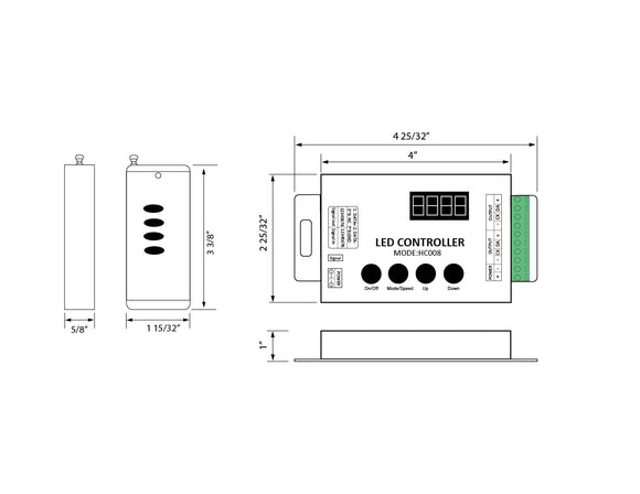
- Dimension: L 5.12", W 2.75", H 0.98"
- Control method: SPI
- Work Environment/IP Rating: Dry location, IP20
- Finish options: Silver
- Certification: RU
- Warranty: 2 Years
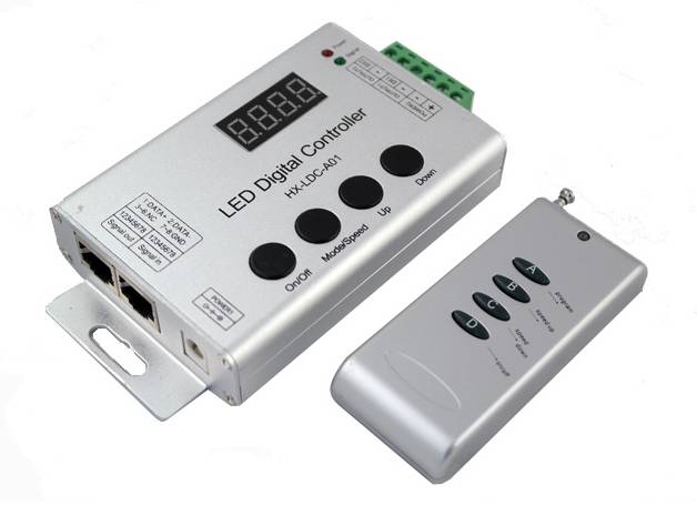
Interface Specifications
Power input interface (port 1):

adopt conventional power transponson as a DC power input interface.
Power Input Interface(port2):

synchronization interface:
adopt standard network line interface,

Signal output interface, adopt male and female connectors with screws

Directions for use
- Connect the load wire well at first, followed by the power wire. Please ensure short circuit can not occur between connecting wires before you turn on the power. Then set the steps as follows.
- Press the "On / off" button to turn off the controller before setting the menu.
- Press the “up”, “down” button one time (two buttons together), LED strip will light up at the moment, which means the device has entered the setting state successfully. Then press the "Mode / Speed" button to get into the menu settings screen.
- The first setting screen is for “Control points setting”. The LED display 4-digit is for the number of control points. To plus or minus the number by pressing the “up” and “down” button (Long pressing can adjust quickly). The factory default is “0050”(50 points).
- Continue to press the "Mode / Speed" button will show “S-HI”, which means for high-speed type IC (like USC1903, WS2811, etc.) only.
- After setting well, press the "On / off" button to save and exit.
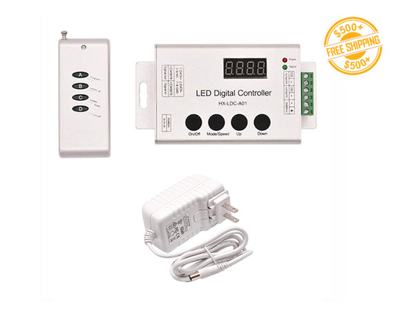
- There are 4 buttons in total on the control panel. The function of each button is as follows:
On/off:It can open or close output.
Mode/Speed :Mode adjustment / speed adjustment function switch (The first LED displays H for model adjustment, shows S for the speed adjustment.)
UP:Mode+/Speed+ button. When in mode regulator function, it is for “Mode+”. When in speed regulator function, it is for “Speed+”.
DOWN:Mode-/Speed- button. When in mode regulator function, it is for “Mode-”. When in speed regulator function, it is for “Speed-”.
Adopt wireless control method, 4keys in total, function of each key as below::

- A: Mode adjustment / speed adjustment function switch (The first LED displays H for model adjustment, shows S for the speed adjustment.)
- B:Mode+/Speed+ button. When in mode regulator function, it is for “Mode+”. When in speed regulator function, it is for “Speed+”.
- C:Mode-/Speed- button. When in mode regulator function, it is for “Mode-”. When in speed regulator function, it is for “Speed-”.
- D:On/Off button: It can open or close output.
- Note: After powering, the red light would bright. And each press, the green light flash one time.
- Synchronous controller system description
Synchronous control system can be made of any number of controller connections. Each of the sub-controller would follow to the first master controller to achieve a permanent synchronous change. And there is not delay.
After connecting the wiring diagram, the sub-controller need not be set. It will be in accordance with the master to controlling the speed and mode change. (That would be not synchronous when powering. You could close and open to be synchronous) When master is working, and the sub-control working well, the green signal light of sub-control would flick. The digital LED display the mode in operation.
Frequently bought together
 |
 |
 |
 |
| All LED Strip Light | All LED Controller | All LED Transformer | All Aluminum Channel |
Compatible Products
Compatible LED strip light:
LED Strip Light - Color Chasing - RGB SPI - High Bright - Dry Location IP20
LED Strip Light - Color Chasing - RGB SPI - High Bright - Wet/Damp Location IP65
Product title
Vendor
$19.99 | $24.99
Product title
Vendor
$19.99 | $24.99
Product title
Vendor
$19.99 | $24.99
Product title
Vendor